Vertical Antenna Comparison

What is the best vertical antenna for a Mesh or LoRa radio?
From the beginning of my tenure with Mesh and LoRa, I have used the RAK4631/RAK19007 combination to homebrew my own hand-held and stand-alone Node devices. Since signal quality is important to LoRa, the antenna is something within my control that I can change to make the systems more effective. I found the plethora of antennas available daunting with wide ranges in advertised performance metrics and prices. I set out to determine which antenna provides the most bang for the buck.
Summary: The TX915-JKD-20, available from Amazon, proved to be the best performer at the best price. Figure 1 shows the tabular summary of the antennas tested.
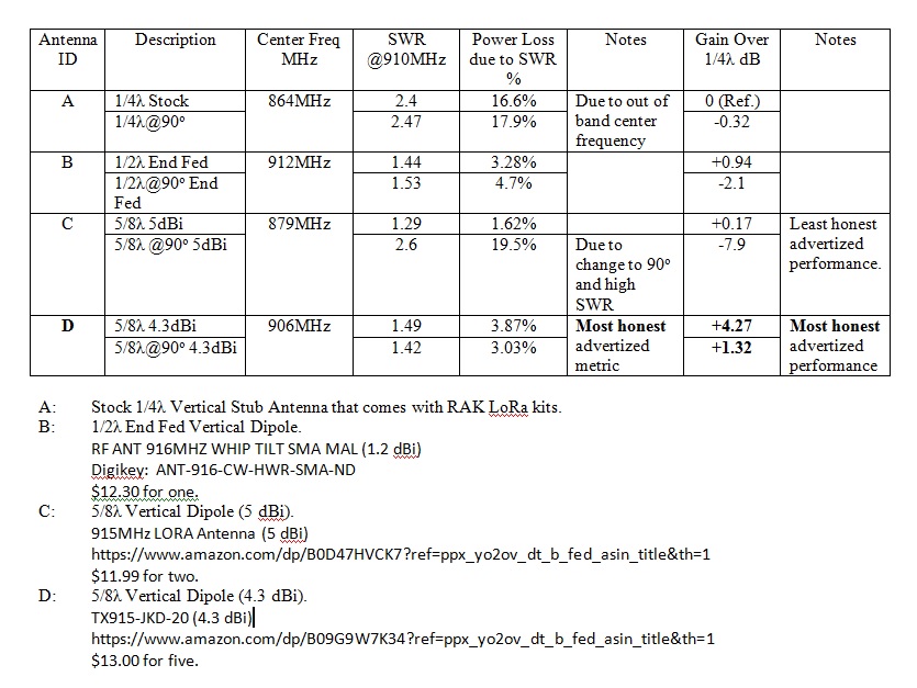
Antennas tested (figure 1):
- A — Stock 1/4λ vertical stub antenna supplied with RAKwireless Mini Meshtastic Starter Kit (Rokland)
- B — 1/2λ end-fed vertical dipole, Linx ANT-916-CW-HWR-SMA-ND (DigiKey) — $12.30 each
- C — 915 MHz LoRa antenna, 5 dBi (Amazon) — $11.99 for two
- D — TX915-JKD-20, 4.3 dBi (Amazon) — $13.00 for five
Discussion
In over-simplified terms, antenna performance is based on getting the most available power from the transmitter headed toward the receiver. There are many factors that impact antenna performance, but two are readily under the user's control: SWR (standing wave ratio) and antenna gain.
SWR is basically a measure of the impedance match between the transmitter output and the antenna input. Any mismatch (some is inevitable in the real world) will result in a percentage of the transmitter power being reflected back into the transmitter final amplifier stages. Reflected power is not available to be radiated out into space, therefore should be minimized where possible. A perfect SWR is 1:1, and acceptable SWR is up to around 1:2. You should start taking corrective action at an SWR of 1:3. The ideal is to use antennas with an SWR as close to 1:1 as possible. The typical "good" antenna is around SWR 1:1.5.
Antenna gain is basically a measure of how much of the transmitter power radiated by the antenna is focused in the desired direction of the receiver antenna. The antenna gain metric is a power ratio of the apparent power compared to the reference power in the logarithmic unit of decibels (dB). Antenna gain does not increase the amount of transmitted power. Rather, by manipulating the radiation pattern of the antenna, it focuses more of the available power toward the receiving antenna. If you imagine that the antenna radiation pattern of a vertical antenna looks like a tire inner tube (doughnut shape), with the vertical antenna in the middle of the doughnut, the power is represented by the outer diameter of the doughnut. The greater the diameter, the more power. The doughnut can be "squished" or flattened by changing the antenna mechanically and/or electrically to produce a change in gain. For instance, common vertical antenna length dimensions are 1/4λ (one fourth wavelength), 1/2λ, 5/8λ, and 1λ. Each antenna has a different radiation pattern (doughnut "flatness"). Antenna element diameters can be manipulated to affect the antenna bandwidth (frequency range of operation). "Squishing" the doughnut flat causes some of the power that is normally radiated up/down from the line between the transmitter antenna and the receiving antenna to be redirected toward that direct line, resulting in more power being received at the antenna relative to the reference.
One of the desirable features in the antenna I was looking for was the ability to bend the antenna at 90° at the antenna base so that the LoRa unit could be laid on its side for stability. It was documented in the literature that in many cases, bending the antenna adversely impacted the SWR of the antenna, and therefore adversely impacting the LoRa unit performance.
Metrics of interest
For this study I was interested in:
- The center frequency of the antenna, advertised and actual. For the U.S. the center frequency should be approximately 915MHz. Antennas designed for the European market are centered around 860MHz.
- Low SWR profile across the LoRa bandwidth.
- Lowest power loss due to SWR at 910MHz.
- Truthful advertised antenna gain (if available).
- Highest measured gain relative to the stock 1/4λ antenna that is supplied with the RAK4631 transceiver.
- The cost per antenna.
Refer back to figure 1 for the tabular summary of the results.
Data collection procedure
I used the NanoVNA (VNA = Vector Network Analyzer) to collect the SWR and antenna gain data.
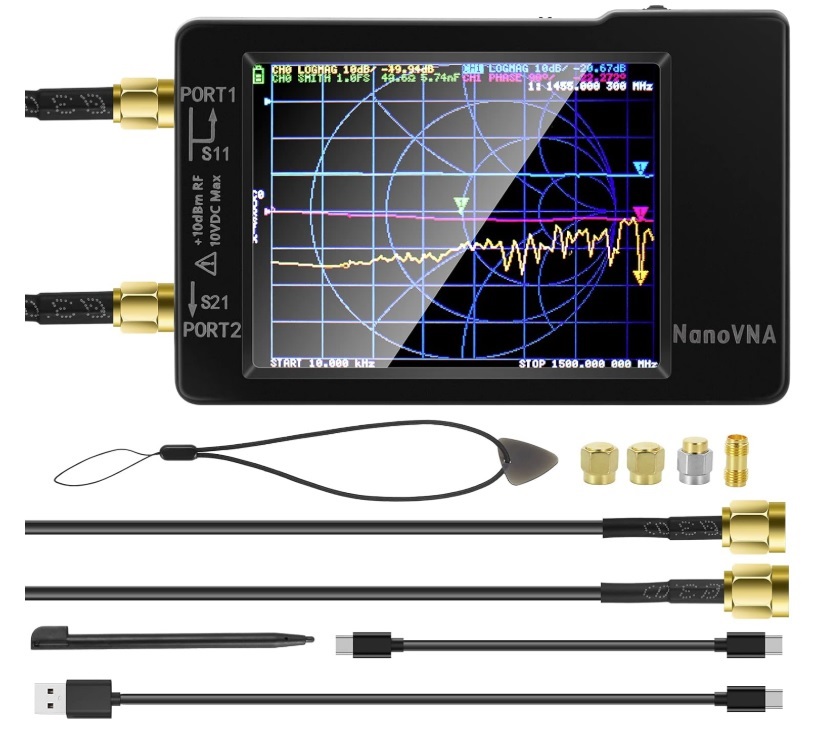
This is a very useful, and relatively inexpensive, unit that does all sorts of RF measurements. For this study I used the SWR and antenna performance features to collect data and produce the graphics in this article. The operation of the NanoVNA is a steep learning curve and beyond the scope of this article but warrants revisiting in the future, perhaps with a how-to article.
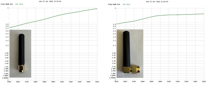
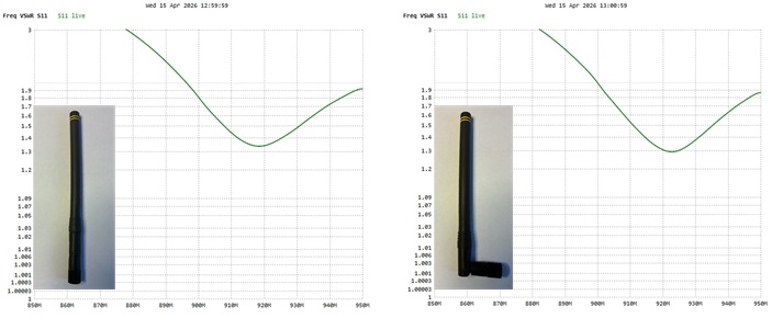
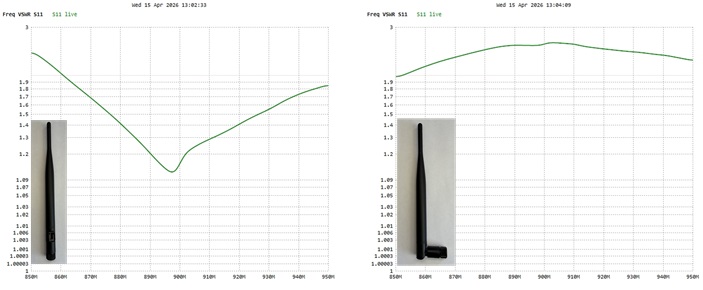
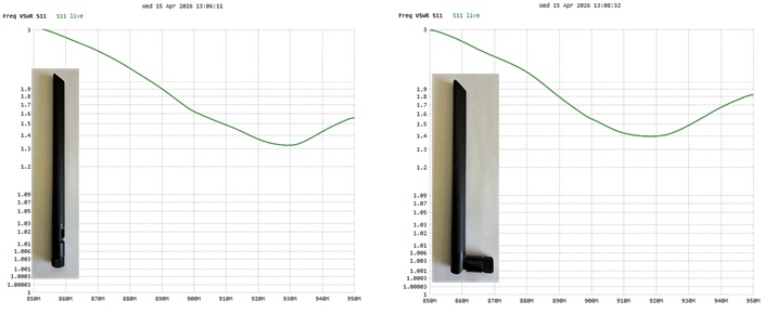
The following SWR graphics depict the antenna center frequency (the lowest point of the SWR curve), the specific SWR at 910MHz, and the SWR profile across the bandwidth being sensed.
Conclusion
Basically it boils down to "trust but verify". The antenna center frequency does not always match what is advertised (European antennas sold as for the U.S. market). The center frequency, and SWR, on some of the antennas tested shifted significantly when the antenna is bent to 90°. In all cases, antenna performance degraded when the antenna was bent 90°, however the degree of degradation depended on the unique antenna. While it can be expected that the advertised gain and the measured gain to be different due to the test conditions, some of the advertisers tended to be overly optimistic in the gain performance.
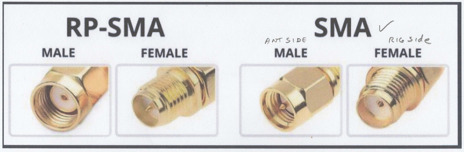
Use caution when ordering antennas: not all SMA connectors are the same. There are RP-SMA (reverse polarity) and regular SMA connectors. I find the illustration in figure 7 very useful when ordering antennas to make sure I get the right polarity.
With all things considered, it appears that the TX915-JKD-20 gives the most bang for the buck.
I would like to offer one final caveat. Mechanical ruggedness of the antennas was not deliberately evaluated in this study. All the antennas appeared to be well constructed with quality materials. During the R&D of a portable Node with the TX915-JKD-20 antenna attached, I inadvertently dropped the unit from about 5 feet above the dirt surface and the antenna snapped clean off at the articulated joint. I suspect that the other articulated verticals would have suffered similar fates had they been dropped. From the ruggedness standpoint, I suspect the stock 1/4λ antenna would be best for situations that are not static (running, hiking, attached to pets, etc.) and accepting the reduced RF performance.
I hope you found the information above worth your time. If more detail is needed, please let me know.
Mark Spencer
NanoVNA information: AURSINC NanoVNA on Amazon