Meshtastic Universal Sensor Interface

Summary
The purpose of this article is to introduce a Meshtastic Universal Sensor Interface template (hardware and software) that uses the Serial Module of Meshtastic as a data link to collect information remotely from sensors connected to a Meshtastic Node. While there is a wide range of sensors included in the portfolio of sensors that are integrated into the Meshtastic firmware and reported out of the Node as telemetry, there are other very capable sensors that are not included (generally very specific, unique, and professionally oriented sensors). Using the Serial Module and UART avoids tampering with the Meshtastic firmware or depending on the Meshtastic development group to modify the firmware for unique sensors. This strategy makes the Universal Sensor Interface independent of the Meshtastic firmware as long as the Serial Module is maintained by the development group.
Basically, I wanted to address a caveat that is mentioned in the Meshtastic documentation: "...other interesting sensor types and use cases we need to add a portnum (sic) for more generic telemetry packets and a second MCU will be required to interact with the sensor and process the data to be sent over the mesh."
Keep in mind, this project is intended to be a template only, I have however used this template to develop working remote sensor systems. It is up to you to cut, paste, plagiarize, and modify the template to your heart's content and make the project your own.
Motivation
A while back I was contacted by a professor from a Great Plains university and ask my opinion if Meshtastic could be used to: 1. track a herd of Bison, and 2. monitor the flow of a seasonal stream. Apparently this was for some research project. I never heard of Meshtastic so it took a while to get up to speed. The answer to the first part of the question was easy, the answer to the second part however was not trivial. The technology required to monitor the condition of a low-flow, intermittent seasonal creek did not match the sensors available in the Meshtastic portfolio of sensors. I set out to address the problem (that is detailed here), naturally since I did not intend to provide a turn-key solution that the university students and faculty could simply apply without additional effort (and that I was expect to pay for and hand over)...I never heard from them again.
The Basic Idea
The universal interface concept is illustrated in Figure 1.
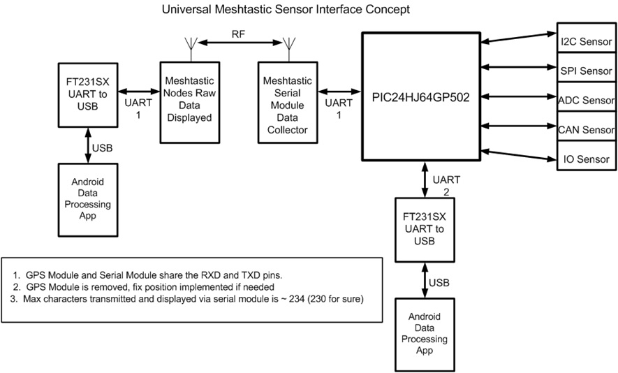
Figure 1.
The two Meshtastic Nodes (remote on the right, base on the left) are in the center of the graphic. A microcontroller is used to control and interface with the sensors, capture the data collected (via the appropriate communications protocol), and convert the data into ASCII format for UART transmission to either to an attached display (Android tablet) or the Meshtastic LoRa (or both). The Meshtastic Serial Module takes the data in ASCII format, adds the appropriate header and footer to form a packet, and transmit the packet to the mesh on channel 0. On the receiving side, the Meshtastic Serial Module takes the received packet and outputs the packet via UART to a serial-to-USB converter (comm. port) then to an attached Android or other computer running a terminal program (Putty or Tera Term) or dedicated display program. There are some technical limitations and conflicts with the schema as noted in the illustration.
Meshtastic Serial Module Packet Format
The visible format of the packets created by the Serial Module is illustrated in Figure 2.

Figure 2.
A DigiView Logic Analyzer was used to interpret the packet format. The DA characters make up the pre/post-amble of the packet. The MS_2:[space] is the Node short name. Sandwiched in-between is the collected data in ASCII text values.
On the receiving end, the processing program (or human) parses away the pre/post-amble characters and performs required calculations on the data.
Microcontroller Interface Between Sensors and Meshtastic
There is a wide range of sensors available on the market with an equally wide range of control/manipulation and communication protocols. This makes taking a "one-size" fits all approach for dealing with sensors impracticable. The following is an incomplete, short list of the communication protocols:
- CAN bus
- MOD bus
- ADC
- SPI
- I2C
- I/O
- UART
- 2-Wire Current Loop
- 3-Wire Variable Voltage
From my embedded processor experience, developers tend to find a family of microcontrollers and stick with that family across various projects if possible. The microcontroller family tends to have similar internal register and resource architectures and code developed for one member of the family can be easily adjusted to work with other family members. In my case, I look to Microchip devices. I chose the Microchip PIC24HJ64 because of this list of resources available on the device that meet the wide range of communication protocols required for this project:
- Multiple-ADCs and I/O pins
- 2-I2Cs
- 2-SPI
- 2-UARTs
- Cam and Mod Modules
- Many others
In addition, programming the PIC with the Microchip MPLabX IDE, PICKit5, and C language is fairly easy to use with powerful debugging features.
USB to Serial Converter
I chose to use the FTDI FT231 device that presents a virtual comm. port to an attached device. The main reason for this choice is that the FTDI family of devices uses very stable Windows and Linux drivers. The device is also wired up with the required resistors (5.1KΩ) so that an OTG (on the go) cable is not required when connected to an Android tablet.
Hardware PCB
The components of the Universal Sensor Interface are mounted on a printed circuit board designed to serve as a "HAT" that is connected on top of a RAK19007 carrier board (Figure 3):
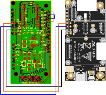
Figure 3.
There are three UART connections (TX, RX, Gnd) between the two boards. There are pin outs on the "HAT" for the various communications protocol resources of the PIC that are connected as appropriate to the sensors being interfaced. The PIC software is authored for the specific sensors being used.
Data Manipulation and Display
Depending on the complexity of the project, data processing can be accomplished on the PIC, some processing on the PIC (within the limits of integer math), more advanced processing on the receiving computer technology (Android or PC), or manually by spreadsheet after the data is received by a terminal program like Putty or Tera Term. This kind of flexibility makes the data manipulation and display very situation dependent.
In the development of the concept I used Tera Term for proof of concept and later authored an Android App to capture and display the data in various formats, stopping short of exploiting the meaning of the data (i.e., doing specific calculations to translate the raw data into metrics). Figure 4 illustrates the screen shot of this Android App.
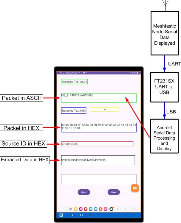
Figure 4.
Okay, so "Where's the beef?"
I applaud your dedication if you made it this far. Attached is a PowerPoint presentation that provides some more specific talking points to describe the Universal Serial Interface effort. Because the project is intended to be "rolling your own", I will provide as many specific details (code, schematics, etc.) as I can upon request. It is my ultimate hope that you will share the idea with any education audience you might have. I firmly believe that Meshtastic/MeshCore is a natural compliment to Mechatronics like curricula and CapStone projects. This project captures the fundamental intent of the LoRa authorization...ISM (Industrial, Scientific, Medical) data links.
Mark Spencer