Is There Such a Thing as a Usable BOT?

While Meshtastic (MT) and MeshCore (MC) have some useful features to evaluate the path and signal quality between two nodes, there are instances where those features fall short; particularly when operating in a remote location without a robust mesh architecture or where there are no "active" mesh participants with the time nor proclivity to respond to signal strength requests. For example, a Scout camp is setting up a temporary, stand alone Meshtastic network to cover the confines of the camp area and the leaders want to verify the coverage using handheld nodes. In this case, a "Ping-Pong" like system would be useful.
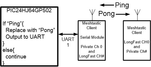
In this article I will present a "Ping-Pong" system that is an example of a simple application that is based on the MT Universal Serial Interface that was the topic of a previous article. In the Ping-Pong application, the PIC of the Universal Serial Interface is programmed to listen for the word "Ping" received via the Serial Module, and if received, the word "Ping" is replaced with the word "Pong", and modified packet is transmitted back on a private channel. This verifies the integrity of the path between the two nodes without the need for other operators to be involved. I view the Ping-Pong system as a piece of mesh and LoRa test equipment. It also demonstrates how the Universal Serial Interface can be used for command and control of attached devices and sensors.
Hardware
The only portion of the Universal Serial Interface HAT PCB that needs to be populated is the PIC24HJ64 microcontroller and associated parts. In the illustration depicted in figure 5 below, the PCB is populated with more than the minimum PIC24HJ64 needed for this project. There are two rows of header pins soldered on the bottom side of the HAT PCB that coincide with the two header receptacles soldered on the top side of the RAK19007 PCB. The right-angle header pins on the side of the HAT PCB are used for programming the PIC with a PICKit5 dongle.
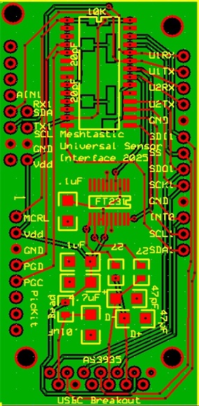
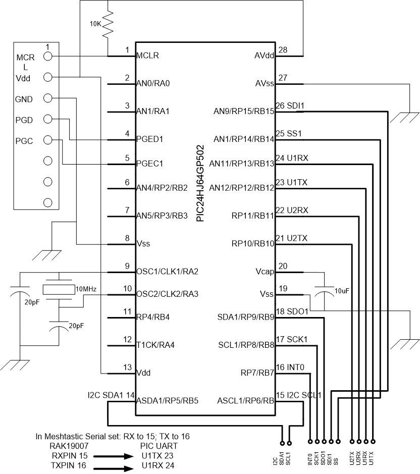
The interconnection to the RAK19007 board includes 3.3 volts, ground, and the UART RX and TX pins.
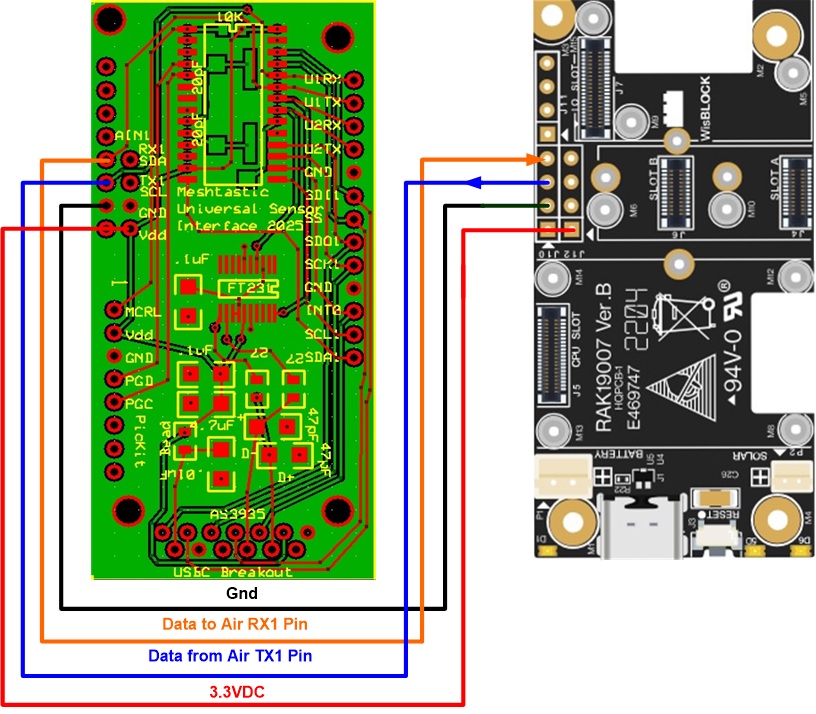
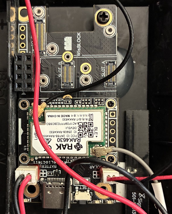
The MT Universal Interface HAT is plugged into the top of the RAK19007 via the header sockets/pins. Spacers and screws can be used to secure the installation of the HAT, particularly for hand-held or mobile systems.
PIC Software
The following code "snippet" is offered to explain the logic of the Ping-Pong Interface. The expanded source code is available upon request.
-
PIC resource set-up and initialization. As with any PIC project, spending time to study resources available and the controller registers that are detailed in the device documentation will pay off big time in the end. In this project the PIC I/O pin assignments to the UART are the main concern.
-
UART configuration. The baud rate (in this case 115200 baud) along with the system clocks need to be configured to match the UART configuration of the Serial Module in MT.
-
Interrupt configuration: In this application there are two interrupts used. A UART interrupt is generated each time a character is received from the Serial Module so that the individual characters within the packet stream can be accumulated into a variable. A Timer 2 (TMR2) interrupt is also used to mitigate a peculiar limitation of dealing with UART data streams.
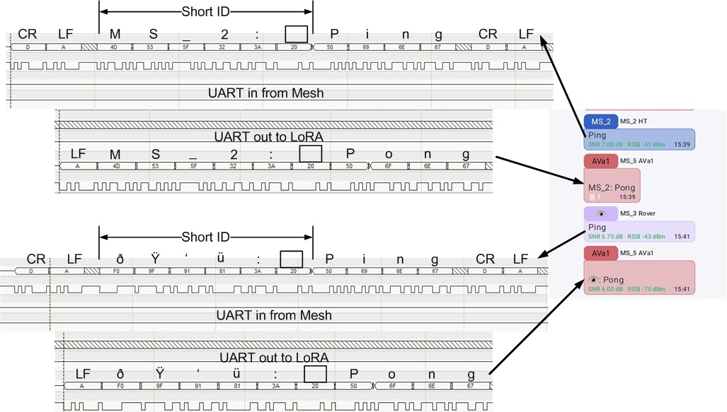
The ASCII characters that make up the packet stream that is produced by the MT Serial Module include a pre and post amble made up of CR and LF characters (Hex D and A), the Node short ID, and the data being transmitted. This packet ASCII stream is depicted in figure 7 below. Because there is no uniquely identifiable character to indicate the end of the packet and the packets can be random in length, one of the timer resources of the PIC is used to generate an interrupt after a defined period during which no characters are being received over the UART. This allows packets of unknown length to be received, the end of the packet being indicated by no additional characters being received during a specific time period. In this case, by experimentation and trial and error, if a character is not received for 4mS, it is assumed that the packet is complete.
The individual characters being received are accumulated into a packet inside of the UART interrupt routine. The end of the packet is determined inside the TMR2 interrupt routine and a new_data variable flag is set to indicate to the Main program that a new packet is ready for processing.
- Main program: Inside the Main program is an infinite loop. Within the loop a new_data flag is checked to see if a new packet is available for processing. If yes, the packet is checked to see if the word "Ping" is included (without this check, every packet received on any channel would be retransmitted clogging up the bandwidth unnecessarily). If the packet includes "Ping", the "Ping" substring is replaced with "Pong", the pre and post ambles are removed (to be added back later by MT during transmission). The amended data is then sent back via UART to the MT Serial Module for transmission over channel 0 (in this case channel 0 should be a private channel, not LongFast). The final step within the loop is to place the PIC program in an idle state to minimize power consumption. An interrupt generated by the UART will wake up the PIC so that the next packet can be received.
I provide the following code snippets with the caveat that I am not a professional coder, I use brute force coding techniques meaning that my code is not elegant nor the most efficient, but it works. The reader is probably far more proficient and will produce more elegant code than I have brain cells enough to author.
//variables
//used in UART
int i=-1;   //char counter
char RX_buf[40];//accumulate characters received

//used in Ping_Pong
const char *remove_ping = "Ping";
const char *replace_pong = "Pong";
char OUT_buf[40];

//resource initialization routines
init_OSC();
init_IO();
init_UART();
Timer2_Init();
initInterrupt();

// Timer 2 Interrupt Service Routine (Timeout Reached)
void _ISR _T2Interrupt(void){
IFS0bits.T2IF = 0;// Clear the Timer 2 interrupt flag
IEC0bits.T2IE = 0;// Disable Timer 2 Interrupt
new_data = true;//update new_data flag
i=-1;//reset UART character counter
}//end T2Interrupt

void _ISR _U1RXInterrupt(void)
/*Since there is no predictable end character for the UART string, a TMR2 interrupt
is used to signal the end of the incoming UART string after a time period with
no character being received.  This works because the incoming string is built
within Meshtastic and then presented for transmission.  This would not work if
the incoming string was being built from keyboard entry.  The length of the TMR2
interrupt delay would ultimately have to be determined experimentally, the delay
presented (~ 4mS) here is a good compromise for 115200 baud.*/
{
IEC0bits.U1RXIE=0;//disable RX1 interrupts
IFS0bits.U1RXIF=0;//clear RX1 interrupt flag
TMR2 = 0x00;// Clear Timer 2 register
IFS0bits.T2IF = 0;// Clear Timer 2 interrupt flag
IEC0bits.T2IE = 1;// Enable Timer 2 interrupt
i++;
RX_buf[i]= U1RXREG;
IEC0bits.U1RXIE=1;
}//end U1RXInterrupt

//Ping-Pong Main routine
while(1)
{
if (new_data){
new_data=false;//reset flag that new string is available
__delay_ms(10000); //delay to allow relays through mesh
//check to see if "Ping" is present in RX_buf, if not skip
if(strstr(RX_buf, remove_ping)!=NULL){
//replace "Ping" with "Pong"
replace_first(RX_buf, remove_ping, replace_pong, OUT_buf);
remove_first_two(OUT_buf); //removes first \r and \n
SendString(OUT_buf); //sends node ID and Pong
//to LoRa Serial Module on channel 0
}
memset(RX_buf, 0, sizeof(RX_buf));//clear RX string array
memset(OUT_buf, 0, sizeof(OUT_buf));//clear OUT string array
}
// This shuts down the CPU core but leaves FCY active for the UART
Idle();
// Execution resumes exactly here when a UART byte is received
__builtin_nop();
}//end Ping-Pong routine
Ping-Pong in operation
With the Ping-Pong system installed in a node, as mentioned, channel 0 of that node should be set up as a private channel. The MT Serial Module will take all packets received over the air, from any channel, and pass the packets out the UART to the microcontroller attached to the UART TX pin. After processing, packets received from that microcontroller attached to the UART RX are only transmitted over the air via channel 0.
Figure 7 illustrates a Ping-Pong exchange from two different hand-held nodes. The top sequence shows a Ping message sent from MS_2, the MT system attaches the pre/post amble plus node ID to the data (Ping) before transmission over the selected channel. The response from AVa1 (which has the Ping-Pong interface installed) is displayed in the Android app that includes the responding node ID (AVal1) along with the originating node ID with Pong replacing Ping. The bottom sequence shows a Ping message sent from a node with a caricature as the ID.
Power consumption
The PIC24HJ64 does consume some power, even when idling between packet receptions. Figure 8 shows the comparison of the battery condition without (red) and then with (purple) the interface installed (the shift in the peak voltage is due to the data being collected on different days when the peak sun angle was different).
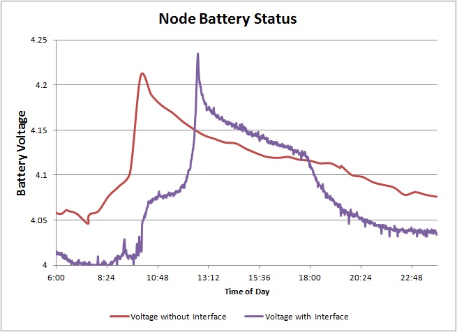
The plot indicates that there is notable power required to run the Ping-Pong interface, however, the solar panel provides sufficient current to bring the battery back to normal values once the panel is out of eclipse.
Summary
My personal learning curve with Meshtastic and MeshCore has been very steep. As I made changes, whether in antennas or exploring coverage in new locations while hiking around, having immediate feedback that I was being heard at "home plate" was important. Since my location has very sparse, if any, MT activity, I was on my own…thus the motivation for the Ping-Pong interface. It has proved very valuable as I continue to "roll my own" MT/MC accessories. I hope you will have the same experience.
If you have questions or need additional details, let me know.
Mark in Coleville